
Gerbmerge with support for metric units of Kicad Gerber files
The excellent tutorials of spaceagerobotics and Ches Koblents made it a lot easier for me to use Kicad together with gerbmerge to panelize a few printed circuit boards which I wanted to submit to Seeed Studio. While the tutorial worked fine using the supplied test files my Kicad files did not work. The reason was, that I designed my PCBs with metric units. Furtunately I found a fork of the original gerbmerge program which included metric support already. However, still my Kicad files did not work.
Gerbview (gerbv) coming with my linux distribution (Debian) was very handy to convert the metric Gerber files to imperial units, but you have to do this layer by layer. While I considered this to be a fall-back option I decided to learn, how gerbmerge is working and try to fix it on my own. To learn Python was on my agenda for quite some time but I had no project, which could motivate me enough. Now gerbmerge, well documented and easy enough to read for me, was the perfect project to learn Python.
I started with the gerbmerge fork from Scott Daniels. First I added support for Seeed Studio from here https://github.com/space-age-robotics/gerbmerge-patched. Over the next two weeks I spent a few hours to modify gerbmerge to panelize my Kicad files. I did not touch the metric routines, which were supplied by Scott Daniels and I hope that I did not change any of his routines accidentially. To add support for Kicad files in metric units I added plenty of extra „if … else“ code blocks to gerbmerge. It might be not the most elegant approach, but I have to admit that I did not have the time to understand every details how gerbmerge works and I was happy that the program now does what I expect it to do. I learnt on my way that Kicad seems to work internally with inches causing some small rounding errors. As a side effect I had a lot of drill sizes which differed only some 1/100 mm. I decided that for my sparetime use it is enough to differenticate drills to 1/10 of a millimeter. Therefore I round the drill sizes but I made it configurable in the layout.cfg-file. This has the advantage that you can decide on your own, whether to round or not to round the drill sizes. The downside is that you have to configure it in the layout-file therefore you have to read the comments of the layout-file carefully.
For your convenience I add some metric Gerber samples which were saved from Kicad. I also add the configuration file which I used to panelize those files (layout-mm-3.3.cfg). 3.3 stands for metric units with 3 decimals, by the way.
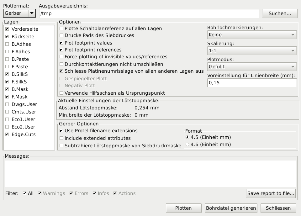
Kicad Settings for Gerber and Drill Files
To make a PCB we need the different layers of the PCB and also the drill file. The layers are stored in the „Gerber“ file format, while the drill files are stored in the „Excellon“ file format.
According to Seeed Studio they evaluate only the following files which should be collected in a .rar or .zip file:
| Extension | Layer |
|---|---|
| pcbname.GTL | Top Copper |
| pcbname.GTS | Top Soldermask |
| pcbname.GTO | Top Silkscreen |
| pcbname.GBL | Bottom copper |
| pcbname.GBS | Bottom Soldermask: |
| pcbname.GBO | Bottom Silkscreen: |
| pcbname.TXT | Drills |
| pcbname.GML/GKO | Board Outline |
The PCB Outline is required. I do not use the output of the edge-cut files, but instead I replace use the file which was generated with the Seeeds patch and which has the extension .oln. I remove the board outline file from gerbmerge and replace it with the .oln file, which I rename to *.gml before I add it to the archive file.
This last step, to omit the BoardOutline file with the markings for the individual panelized boards and replace it with the general outline file (*.oln) from the gerbmerge Seeeds patch, is my interpretation of Seeed Studios online order form where they have a separate selection field for Panelized PCBs. I would assume that the extra amount they charge for panelized pcbs is caused by the extra step to separate the boards. If you separate the boards yourself, like I do, you can save this costs. To see the outline of the files use the option “CutLineLayers” in the layout.cfg file.
# Which layers to draw cut lines on. Omit this option or set to 'None' for no

# cut lines. Cut lines are borders around each job that serve as guides for

# cutting the panel into individual jobs. Option 'CutLineWidth' sets the

# thickness of these cut lines.

#

# NOTE: Layer names are ALL LOWERCASE, even if you define them with uppercase

# letters below.

CutLineLayers = *topsilkscreen,*bottomsilkscreen
This generates the outline of the boards on the silk screens and you can cut along these lines.
You can select or deselect the layers easily according to your needs with the checkboxes on the left side. I selected the 4.5 format, but did not test the 4.6 format so far. However, I would assume that it will work, too.
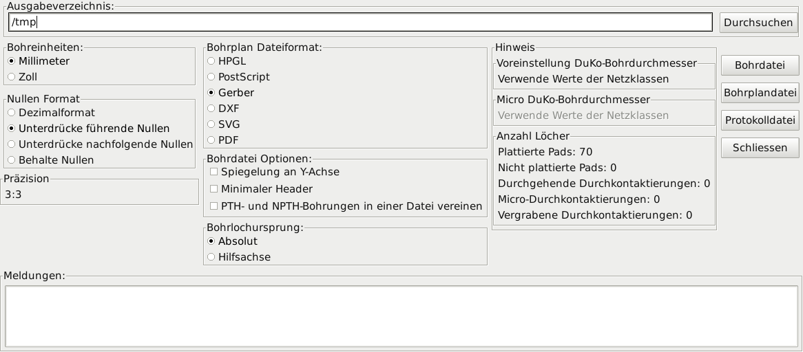
In addition we need the drill file („Bohrdatei generieren“): Drills=*.drl
Select the same unit (mm !) for the drill file as you selected for the schematics. Suppressing the leeding zeros seems to comply with the requirements of a lot of PCB services. If you make only a drill file („Bohrdatei“) then the file format selection in the middle column has no influence as drill files are always in Excellon format. The FAQ of OshPark PCB suggests to use absolute coordinates for the drill file. I would assume that this also works for other manufacturers.
Panelizing PCBs for Seeed Studio Using Kicad
According to spaceagerobotics Seeed requires an outline for the entire panel to be present on all layers, otherwise, they will offer to change your order for multiple, separate boards, which defeats the entire purpose. Therefore, his patch is included in my fork of gerbmerge already. If you are interested how this is achieved then have a look at the diff file of these patches to the config.py and gerbmerge.py files.
In order to use gerbmerge you have to edit the configuration file layout.cfg. I supplied an example for Kicad files in metric units (= layout-mm-3.3.cfg). To make it easier to identify my additions, I use my initials as the beginning of my comments (KHK: ). In my example I used a directory („project“ folder) where I save the resulting merged-Gerber-files and saved each pcb which is included in a separate subdirectory below this „project“ folder.
Edit the following lines in the layout.cfg file:
    # Optional indication of the number of decimal places in input Excellon drill

    # files. The default is 4 which works for recent versions of Eagle (since

    # version 4.11r12), as well as Orcad and PCB. Older versions of Eagle use 3

    # decimal places.

    # KHK: Kicad drill files in metric units use 3.3 format, which means

    # that the ExcellonDecimals should be 3 here.

    ExcellonDecimals = 3

    # Units - We must specify whether files use imperial units (inch) or metric units (mm)

    MeasurementUnits = mm

    #MeasurementUnits = inch


    # KHK: do we import from KiCAD files which are in metric units? If yes, then check here
    "true" (= 1) and

    # put the right number of decimals into the setting "ExcellonDecimals" a few lines above

    # KHK: true = 1, false = 0

    KicadFilesInMetricUnits = 1

    #KicadFilesInMetricUnits = 0


    # KHK: using metric units it does not make sense to use 1/1000 mm as drill size. Due to rounding errors in

    # KHK: KiCAD for example we would get a lot of different drills.

    # KHK: I am no PCB expert, but base on my experience it does not make much sense to declare drill sizes

    # KHK: with a precision which is better then 1/10 of a mm.

    # KHK: true = 1, false = 0

    roundDrillSize = 1

    #roundDrillSize = 0
For the other options look at the sample files layout*.cfg which I include with my test data.
To generate the panel with automatic placement of the boards, invoke gerbmerge:
path/to/python path/to/gerbmerge.py panel.layout
It is also possible to omit the automatic placement and force gerbmerge to use your arrangement of the pcbs using a panel.cfg file. I did not test this alternative yet as the automatic placement worked fine for my projects so far. path/to/python path/to/gerbmerge.py panel.cfg panel.layout
You will first be presented with a warning about the lack of warranty, as in the first image below. Enter ‘Y’ to continue. To suppress this annoying message edit the file config.py and set the variable skipdisclaimer to 1.
'skipdisclaimer': 1, # set to 1 to skip disclaimer prompt
Have a look at the output in your Gerber viewer to make sure that the results are as you expect them to be.
Download
You can download my fork of Gerbmerge from Github.